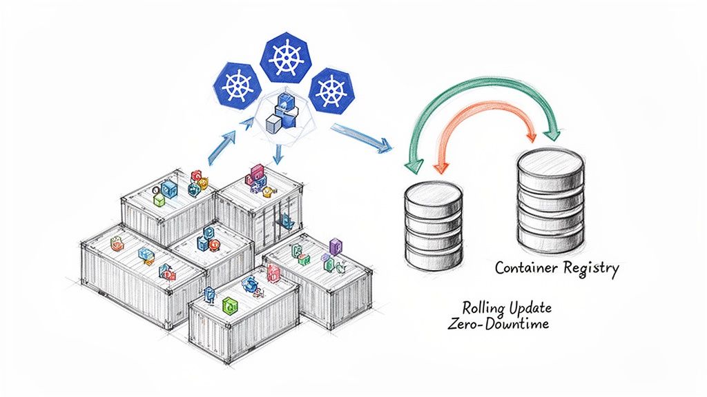
Kubernetes deployment strategies are the methodologies used to upgrade a running application to a new version. The choice of strategy dictates the trade-offs between release velocity, risk exposure, and resource consumption during an update.
Selecting the appropriate strategy is a critical architectural decision. A default RollingUpdate is suitable for many stateless applications where temporary version mixing is acceptable. However, for a critical service update, a Canary release is superior, as it allows for validating the new version with a small percentage of live traffic before proceeding. This decision directly impacts system reliability and the end-user experience.
Why Your Kubernetes Deployment Strategy Matters
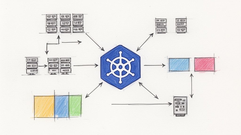
In cloud-native architectures, application deployment is a sophisticated process that extends far beyond a simple stop-and-start update. The chosen strategy is a fundamental operational decision that defines how the system behaves during a version change.
The core tension is between deployment velocity and production stability. An ill-suited strategy can introduce downtime, user-facing errors, or catastrophic failures. Conversely, the right strategy, properly automated, empowers engineering teams to ship features with higher frequency and confidence.
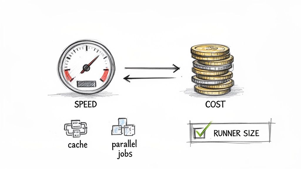
The Core Trade-Offs: Speed, Risk, and Cost
Every deployment strategy involves a trade-off between three primary factors. A clear understanding of these is the first step toward selecting the right approach for a given workload.
- Speed: The time required to fully roll out a new version. A Recreate deployment is fast to execute but incurs downtime.
- Risk: The potential impact radius if the new version contains a critical bug. Strategies like Canary and Blue/Green are designed to minimize this blast radius.
- Cost: The additional compute and memory resources required during the update process. A Blue/Green deployment, for example, doubles the resource footprint of the application for the duration of the deployment.
This chart visualizes the decision matrix for these trade-offs.
As shown, advanced strategies typically exchange higher resource cost and operational complexity for lower risk and zero downtime. This guide provides the technical details required to implement each of these strategies effectively.
A Quick Guide to Kubernetes Deployment Strategies
This table offers a high-level comparison of the most common deployment strategies, functioning as a quick reference for their respective trade-offs and ideal technical scenarios.
| Strategy | Downtime | Resource Cost | Ideal Use Case |
|---|---|---|---|
| Recreate | Yes | Low | Development environments, batch jobs, or applications where downtime is acceptable. |
| Rolling Update | No | Low | Stateless applications where running mixed versions temporarily is not problematic. |
| Blue/Green | No | High | Critical stateful or stateless applications requiring instant rollback and zero downtime. |
| Canary | No | Medium | Validating new features or backend changes with a small subset of live traffic before a full rollout. |
| A/B Testing | No | Medium | Comparing multiple feature variations against user segments to determine which performs better against business metrics. |
| Shadow | No | High | Performance and error testing a new version with real production traffic without impacting users. |
This table serves as a starting point. The following sections provide a detailed technical breakdown of each strategy.
The Foundational Strategies: Recreate and Rolling Updates
Kubernetes provides two native deployment strategies implemented directly within the Deployment controller: Recreate and Rolling Update. These are the foundational patterns upon which more advanced strategies are built. A thorough understanding of their mechanics is essential before adopting more complex release patterns.
The Recreate Strategy Explained
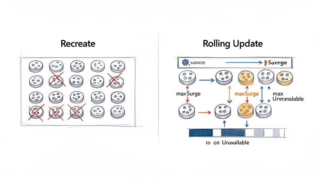
The Recreate strategy is the most straightforward but also the most disruptive. It follows a "terminate-then-launch" sequence: all running pods for the current version are terminated before any pods for the new version are created. This ensures that only one version of the application is ever running, eliminating any potential for version incompatibility issues.
The primary trade-off is guaranteed downtime. A service outage occurs during the interval between the termination of the old pods and the new pods becoming ready to serve traffic.
This makes the Recreate strategy unsuitable for most production, user-facing services. Its use is typically confined to development environments or for workloads that can tolerate interruptions, such as background processing jobs or periodic batch tasks.
The core principle of the Recreate strategy is "stop-before-start." It prioritizes version consistency over availability, making it a predictable but high-impact method for updates.
Implementation requires a single line in the Deployment manifest.
apiVersion: apps/v1
kind: Deployment
metadata:
  name: my-app-deployment
spec:
  replicas: 3
  strategy:
    type: Recreate # Specifies the deployment strategy
  template:
    metadata:
      labels:
        app: my-app
    spec:
      containers:
      - name: my-app-container
        image: my-app:v2 # The new container image version
The Rolling Update Strategy
The Rolling Update is the default deployment strategy for Kubernetes Deployments. It provides a graceful, zero-downtime update by incrementally replacing old pods with new ones. The controller ensures that a minimum number of application instances remain available to serve traffic throughout the process.
The sequence is managed carefully: Kubernetes creates a new pod, waits for it to pass its readiness probe, and only then terminates one of the old pods. This cycle repeats until all old pods are replaced.
This incremental approach offers a strong balance between update velocity and service availability, making it the standard for a vast number of stateless applications.
Fine-Tuning Your Rollout
Kubernetes provides two parameters within the rollingUpdate spec to fine-tune the behavior of the update: maxUnavailable and maxSurge.
maxUnavailable: Defines the maximum number of pods that can be unavailable during the update. This can be specified as an absolute number (e.g.,1) or a percentage (e.g.,25%). A lower value ensures higher availability at the cost of a slower rollout.maxSurge: Defines the maximum number of additional pods that can be created above the desired replica count. This can also be an absolute number or a percentage. This allows the controller to create new pods before terminating old ones, accelerating the rollout at the cost of temporarily increased resource consumption.
Here is a practical configuration example:
apiVersion: apps/v1
kind: Deployment
metadata:
  name: my-app-deployment
spec:
  replicas: 10
  strategy:
    type: RollingUpdate
    rollingUpdate:
      maxUnavailable: 1 # Guarantees at most 1 pod is down at any time
      maxSurge: 2       # Allows up to 2 extra pods (12 total) during the update
With these settings for a 10-replica Deployment, Kubernetes ensures that at least 9 pods (10 - 1) are always available. It may temporarily scale up to 12 pods (10 desired + 2 surge) to expedite the update. You can monitor the progress of the rollout using kubectl rollout status deployment/my-app-deployment.
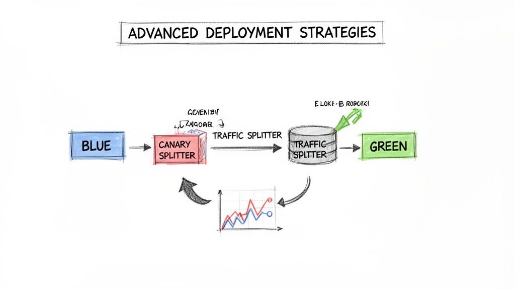
Achieving Flawless Releases with Blue/Green Deployments
While a Rolling Update minimizes downtime, it creates a period where both old and new application versions are running concurrently. This can introduce subtle bugs or compatibility issues. For mission-critical applications requiring instant, predictable rollbacks and zero risk of version mixing, the Blue/Green deployment strategy is the superior choice.
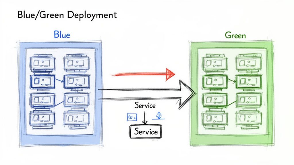
The concept involves maintaining two identical, isolated production environments, designated 'Blue' (current version) and 'Green' (new version). At any given time, live traffic is directed to only one environment—for example, Blue. The Green environment remains idle or is used for final-stage testing.
When a new version is ready for release, it is deployed to the idle Green environment. This allows for comprehensive testing—smoke tests, integration tests, and performance validation—against a production-grade stack without affecting any users.
Once the Green environment is fully validated, a routing change instantly redirects all live traffic from Blue to Green.
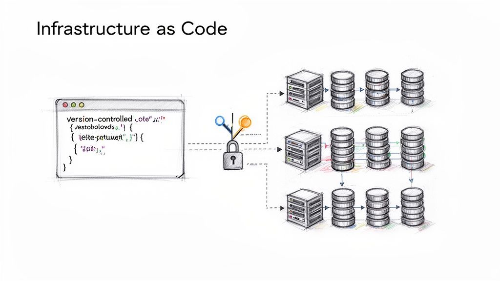
Implementing Blue/Green with Kubernetes Services
In Kubernetes, Blue/Green deployments are implemented by manipulating the label selectors of a Service. A Kubernetes Service provides a stable endpoint for an application, routing traffic to pods matching its selector. The strategy hinges on atomically updating this selector to point from the Blue deployment to the Green deployment.
This requires two separate Deployment manifests, differing only by a version label.
The Blue Deployment for version v1.0.0:
apiVersion: apps/v1
kind: Deployment
metadata:
  name: my-app-blue
spec:
  replicas: 3
  selector:
    matchLabels:
      app: my-app
      version: v1.0.0
  template:
    metadata:
      labels:
        app: my-app
        version: v1.0.0 # Blue version label
    spec:
      containers:
      - name: my-app-container
        image: my-app:v1.0.0
The Green Deployment for the new version v2.0.0:
apiVersion: apps/v1
kind: Deployment
metadata:
  name: my-app-green
spec:
  replicas: 3
  selector:
    matchLabels:
      app: my-app
      version: v2.0.0
  template:
    metadata:
      labels:
        app: my-app
        version: v2.0.0 # Green version label
    spec:
      containers:
      - name: my-app-container
        image: my-app:v2.0.0
The Service initially directs traffic to the Blue deployment.
apiVersion: v1
kind: Service
metadata:
  name: my-app-service
spec:
  selector:
    app: my-app
    version: v1.0.0 # Initially targets the Blue deployment
  ports:
    - protocol: TCP
      port: 80
      targetPort: 8080
To execute the cutover, you patch the Service to change its selector. The command kubectl patch service my-app-service -p '{"spec":{"selector":{"version":"v2.0.0"}}}' atomically updates the selector.version field from v1.0.0 to v2.0.0, rerouting all traffic instantly.
Benefits and Drawbacks of Blue/Green
The benefits of this Kubernetes deployment strategy are significant for stability-focused teams.
- Zero Downtime: The traffic switch is atomic and transparent to users.
- Instant Rollback: If issues are detected in the Green environment, rollback is achieved by patching the Service selector back to the Blue version.
- Production Testing: The new release can be fully validated in an isolated, production-identical environment before receiving live traffic.
This reliability is crucial. With 66% of organizations now running Kubernetes in production according to the CNCF Annual Survey 2023, robust deployment automation is a necessity.
The main drawback is cost. A Blue/Green deployment requires you to run double the infrastructure for the duration of the release process, which can be expensive.
The primary disadvantage is resource cost, as it requires enough cluster capacity for two full production environments simultaneously. This can be mitigated with cluster autoscaling or by treating the old Blue environment as the staging ground for the next release. For a deeper look, see our guide on the essentials of a Blue/Green deployment.
Minimizing Risk with Canary and Progressive Delivery
Blue/Green deployments provide a strong safety net, but the all-or-nothing traffic cutover can still be high-stakes. If a latent bug exists, 100% of users are exposed simultaneously. Canary deployments offer a more gradual, data-driven approach to de-risking releases by exposing the new version to a small subset of users first.
The strategy involves routing a small percentage of live traffic (e.g., 5%) to the new version (the "canary") while the majority remains on the stable version. Key performance indicators (KPIs) like error rates, latency, and resource utilization are monitored for the canary instances.
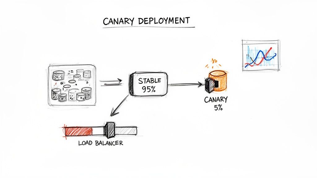
If the canary performs as expected, traffic is incrementally shifted to the new version until it handles 100% of requests. This "test in production" methodology validates changes with real user traffic, minimizing the blast radius of any potential issues.
Implementing Canary with a Service Mesh
Native Kubernetes objects do not support fine-grained, percentage-based traffic splitting. This functionality requires an advanced networking layer, typically provided by a service mesh like Istio or Linkerd, or a capable ingress controller. These tools provide the necessary traffic management capabilities.
With Istio, this is achieved using a VirtualService Custom Resource Definition (CRD). You deploy both the stable and canary versions as separate Deployments and then use a VirtualService to precisely route traffic between them based on weights.
This VirtualService manifest routes 90% of traffic to the stable v1 and 10% to the canary v2:
apiVersion: networking.istio.io/v1beta1
kind: VirtualService
metadata:
  name: my-app-virtualservice
spec:
  hosts:
    - my-app-service
  http:
  - route:
    - destination:
        host: my-app-service
        subset: v1
      weight: 90 # 90% of traffic to stable
    - destination:
        host: my-app-service
        subset: v2
      weight: 10 # 10% of traffic to canary
Based on monitoring data, an operator can update the weights to 50/50, then 0/100 to complete the rollout. If issues arise, setting the v1 weight back to 100 executes an instant rollback.
Progressive Delivery with Argo Rollouts
Manual management of Canary deployments is error-prone. Progressive Delivery tools like Argo Rollouts automate this process. Argo Rollouts introduces a Rollout CRD, an alternative to the standard Deployment object, which orchestrates advanced deployment strategies like Canary and Blue/Green.
Argo Rollouts automates Canary releases by linking the traffic shifting process directly to performance metrics. It can query a monitoring system like Prometheus and automatically promote or roll back the release based on the results, removing manual guesswork.
The entire release strategy is defined declaratively within the Rollout manifest, including traffic percentages, pauses for analysis, and success criteria based on metrics. Argo Rollouts integrates with service meshes and ingress controllers to manipulate traffic and with observability tools like Prometheus to perform automated analysis.
Consider this Rollout manifest snippet:
apiVersion: argoproj.io/v1alpha1
kind: Rollout
metadata:
  name: my-app-rollout
spec:
  strategy:
    canary:
      steps:
      - setWeight: 10
      - pause: { duration: 5m } # Wait 5 minutes for metrics to stabilize
      - setWeight: 25
      - pause: {} # Pause indefinitely until manually promoted
This configuration defines a multi-step rollout, providing opportunities for observation at each stage. This makes advanced deployment strategies more accessible and significantly safer.
Canary vs. A/B Testing
While both involve traffic splitting, Canary deployments and A/B testing serve different purposes.
- Canary Deployments are for technical risk mitigation. The goal is to validate the stability and performance of a new software version under production load. Traffic is typically split randomly by percentage.
- A/B Testing is for business hypothesis validation. The goal is to compare different feature variations to determine which one better achieves a business outcome (e.g., higher conversion rate). Traffic is routed based on user attributes (e.g., cookies, headers). A/B testing often relies on effective feature toggle management.
Enterprise Kubernetes adoption has reached 96%, and Kubernetes now holds a 92% market share in orchestration. You can discover more insights about Kubernetes adoption trends on Edge Delta. This widespread adoption drives the need for safer, automated release practices like Canary deployments.
Validating New Code with Shadow Deployments
A Shadow Deployment (or traffic mirroring) is an advanced strategy for testing a new application version with live production traffic without affecting end-users. It offers the highest fidelity for pre-release validation.
The mechanism involves deploying the new "shadow" version alongside the stable production version. The networking layer is configured to send a copy of live production traffic to the shadow service. The shadow service processes these requests, but its responses are discarded. Users only ever receive responses from the stable version, making the entire test invisible and risk-free.
This provides invaluable data on how the new code performs under real-world load and with real data patterns, allowing teams to analyze performance, check for errors, and validate behavior before a full rollout.
How Shadow Deployments Work in Kubernetes
Standard Kubernetes objects lack the capability for traffic mirroring. This functionality is a feature of advanced networking layers provided by a service mesh like Istio. Istio's traffic management features allow for the creation of sophisticated routing rules to duplicate requests.
The setup requires two Deployments: one for the stable version (v1) and another for the shadow version (v2). An Istio VirtualService is then configured to route 100% of user traffic to v1 while simultaneously mirroring that traffic to v2.
This Istio VirtualService manifest demonstrates the configuration:
apiVersion: networking.istio.io/v1beta1
kind: VirtualService
metadata:
  name: my-app-shadowing
spec:
  hosts:
    - my-app-service
  http:
  - route:
    - destination:
        host: my-app-service
        subset: v1 # Primary destination for 100% of user-facing traffic
    mirror:
      host: my-app-service
      subset: v2 # Mirrored (shadow) destination
    mirrorPercentage:
      value: 100.0 # Specifies that 100% of traffic should be mirrored
A breakdown of the configuration:
- The
route.destinationblock ensures all user-facing requests are handled by thev1service subset. - The
mirrorblock instructs Istio to send a copy of the traffic to thev2service subset. mirrorPercentageis set to100.0, meaning every request tov1is duplicated tov2.
The mirrored traffic is handled in a "fire-and-forget" manner. The service mesh does not wait for a response from the shadow service, minimizing any potential latency impact on the primary request path.
Key Benefits and Operational Needs
The primary benefit is risk-free production testing, which helps answer critical questions before a release:
- Does the new version introduce performance regressions under production load?
- Are there unexpected errors or memory leaks when processing real-world data?
- Can the new service handle the same traffic volume as the stable version?
A Shadow Deployment is the closest you can get to a perfect pre-release test. It validates performance and correctness using real production traffic, effectively eliminating surprises that might otherwise only appear after a full rollout.
This strategy demands a mature observability stack. Without robust monitoring, logging, and tracing, the mirrored traffic generates no value. Engineering teams must be able to compare key performance indicators (KPIs) between the production and shadow versions. This typically involves dashboarding:
- Latency: Comparing p95 and p99 request latencies.
- Error Rates: Monitoring for spikes in HTTP 5xx error rates in the shadow service.
- Resource Consumption: Analyzing CPU and memory usage for performance bottlenecks.
This data enables an evidence-based decision to promote the new version or iterate further, all without any impact on the end-user experience.
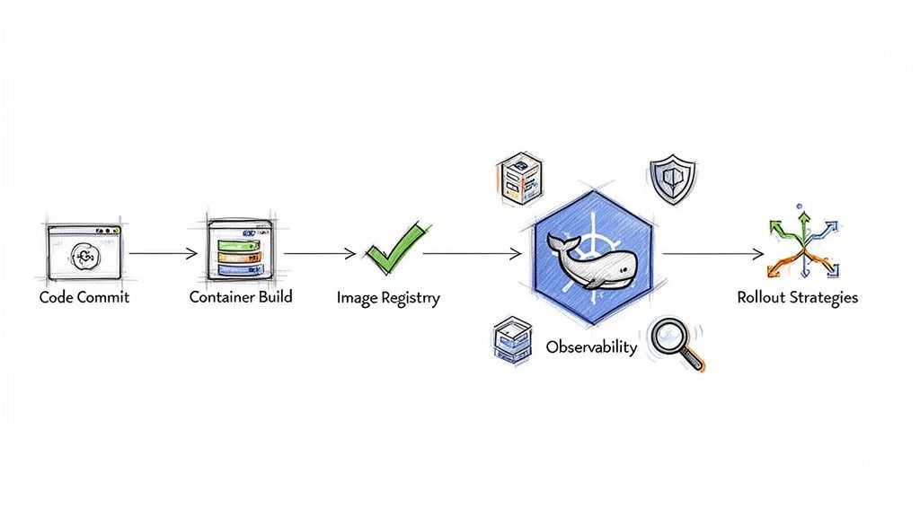
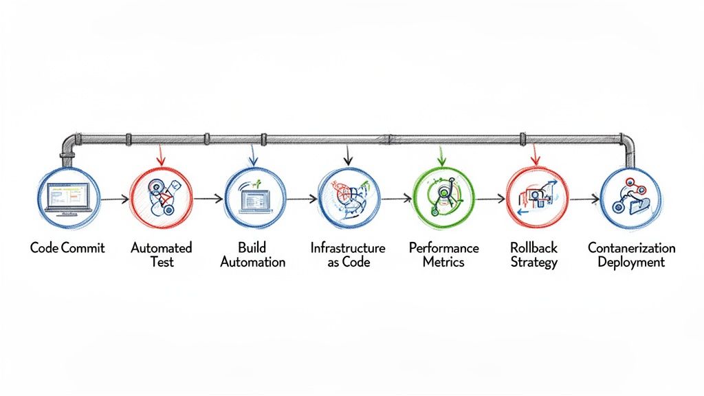
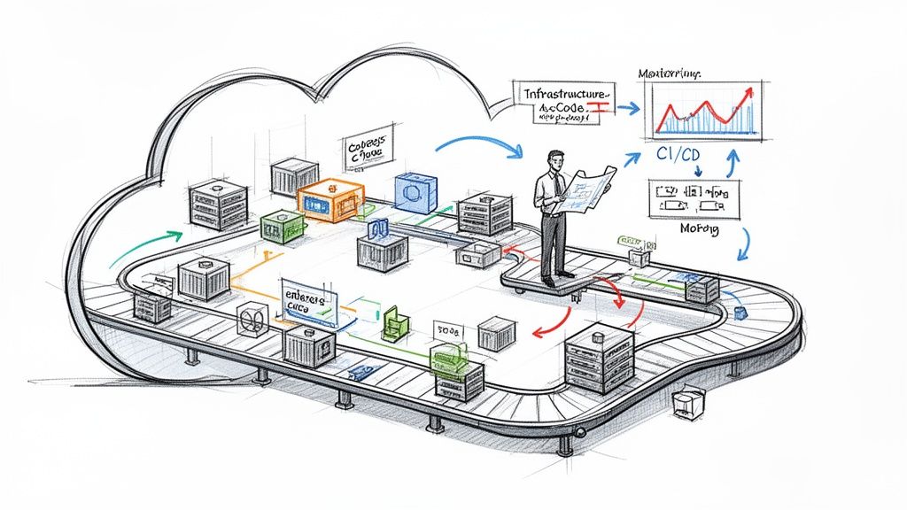
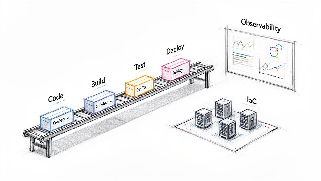
Automating Deployments with CI/CD and Observability
The effectiveness of a Kubernetes deployment strategy is directly proportional to the quality of its automation. Manual execution of traffic shifts or performance analysis is slow and error-prone. True operational excellence is achieved when these advanced strategies are integrated directly into a CI/CD pipeline.
This integration creates a resilient, intelligent, and autonomous release process.
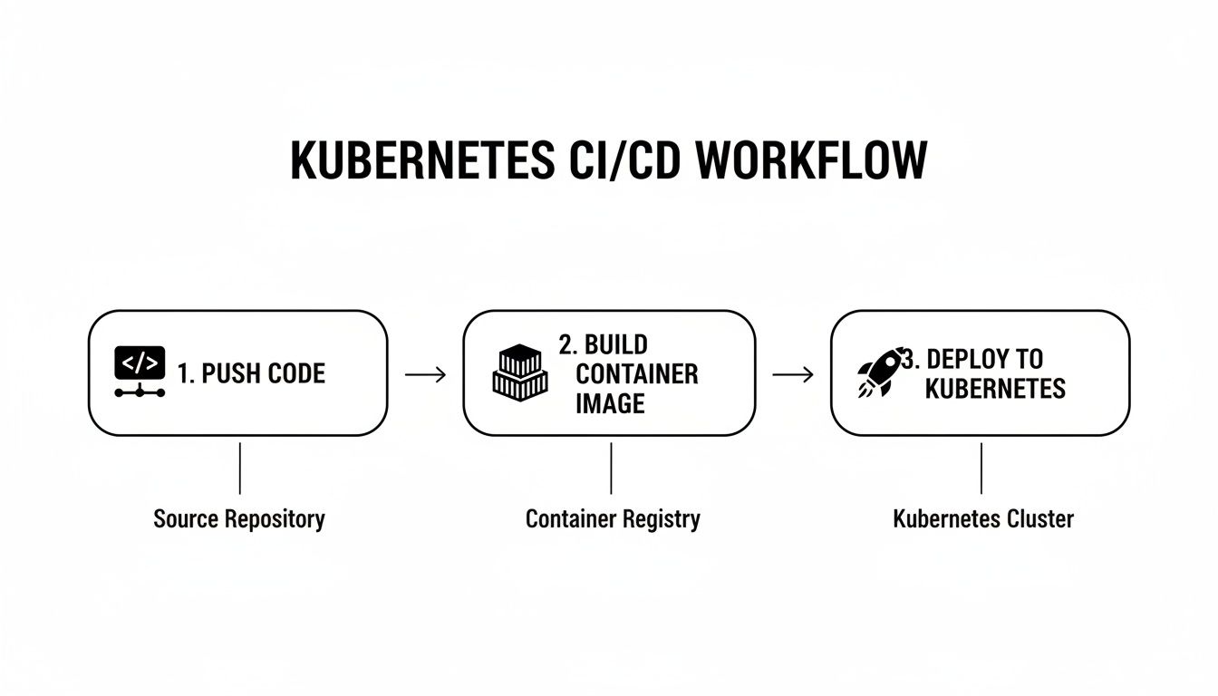
CI/CD platforms like Jenkins, GitLab CI, or GitOps tools like Argo CD orchestrate the entire release workflow. They can be configured to automatically trigger deployments, manage Blue/Green traffic switches, or execute phased Canary rollouts. This automation eliminates human error and ensures repeatable, predictable releases. For more on this topic, refer to our guide on building a robust Kubernetes CI/CD pipeline.
The Critical Role of Observability
Automation without observability is dangerous. A CI/CD pipeline can automate the deployment of a faulty release just as easily as a good one. A resilient system pairs automation with a comprehensive observability stack, using real-time data as an automated quality gate.
This involves leveraging metrics, logs, and traces to programmatically decide whether a deployment should proceed or be automatically rolled back.
An automated deployment pipeline that queries observability data is the cornerstone of modern, high-velocity software delivery. It transforms deployments from a hopeful push into a controlled, evidence-based process.
Consider a Canary deployment managed by Argo Rollouts. The pipeline itself performs the analysis. Using an AnalysisTemplate, it automatically queries a data source like Prometheus to validate the health of the canary against predefined Service Level Objectives (SLOs).
This automated feedback loop relies on key signals:
- Metrics (Prometheus): Tracking application vitals like HTTP
5xxerror rates and p99 request latency. - Logs (Loki): Querying for specific error messages or log patterns that indicate a problem.
- Traces (Jaeger): Analyzing distributed traces to identify performance degradation in downstream services caused by the new release.
Creating an Intelligent Delivery Pipeline
Combining CI/CD automation with observability creates an intelligent delivery system.
For example, an Argo Rollouts AnalysisTemplate can be configured to query Prometheus every minute during a Canary analysis step. The query might check if the 5xx error rate for the canary version exceeds 1% or if its p99 latency surpasses 500ms.
If either SLO is breached, Argo Rollouts immediately halts the deployment and triggers an automatic rollback, shifting 100% of traffic back to the last known stable version. No human intervention is required.
This automated safety net empowers teams to increase their deployment frequency with confidence, knowing the system can detect and react to failures faster than a human operator. The overall effectiveness of this pipeline can be measured by tracking industry-standard benchmarks like the DORA Metrics, providing a quantitative assessment of your software delivery performance.
Got Questions? We've Got Answers.
Implementing Kubernetes deployment strategies often raises practical questions. Here are answers to some of the most common inquiries from DevOps and platform engineering teams.
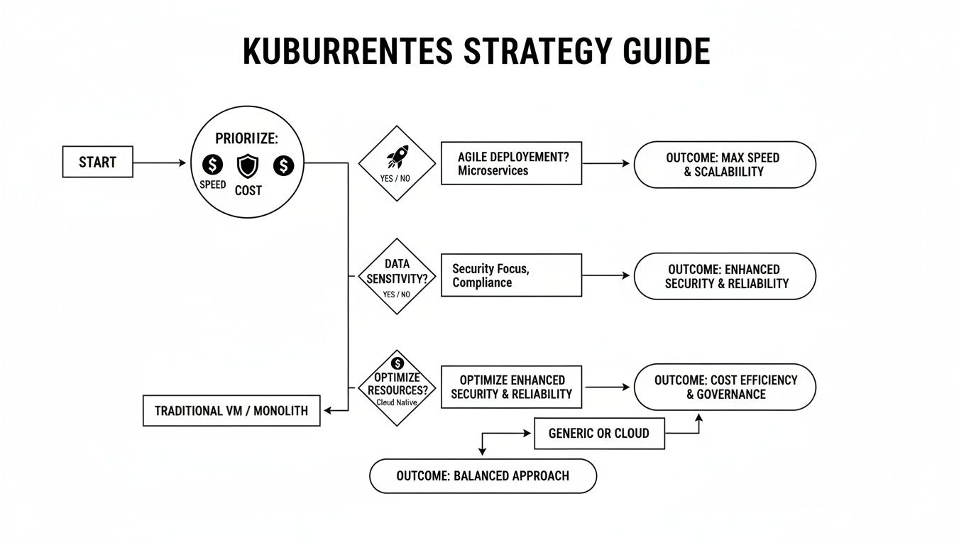
How Do I Choose the Right Deployment Strategy?
The optimal strategy depends on the specific context of the application: its architecture, criticality, and tolerance for risk and downtime.
- For dev/test environments or internal tools: Recreate is often sufficient. Brief downtime is acceptable.
- For most stateless production applications: The default Rolling Update is the standard. It provides zero-downtime updates with minimal complexity.
- For critical services requiring instant rollback: Blue/Green is the best choice. The atomic traffic switch and simple rollback mechanism provide maximum safety.
- For high-risk changes or major feature releases: A Canary deployment is ideal. It allows for validating performance and stability with a small subset of real users before a full rollout.
Think of it like this: start with your risk profile. The higher the cost of failure, the more sophisticated your strategy needs to be. You'll naturally move from simple rollouts to carefully controlled releases like Canary.
What Tools Do I Need for the Fancy Stuff?
While Kubernetes natively supports Recreate and Rolling Update, advanced strategies require additional tooling for traffic management and automation.
A service mesh is a prerequisite for fine-grained traffic control. Tools like Istio or Linkerd provide the control plane necessary to split traffic by percentage for Canary releases or to mirror traffic for Shadow deployments.
A progressive delivery controller is essential for automation. Tools like Argo Rollouts or Flagger automate the release lifecycle. They integrate with service meshes and observability platforms to analyze, promote, or roll back a release based on predefined metrics and success criteria.
Can I Mix and Match Deployment Strategies in the Same Cluster?
Yes, and you absolutely should. A one-size-fits-all approach is inefficient. The most effective platform engineering strategy is to select the right deployment method for each individual service based on its specific requirements.
A typical microservices application running on a single Kubernetes cluster might use a hybrid approach:
- A Rolling Update for a stateless API gateway.
- A Blue/Green deployment for a critical, stateful service like a user authentication module.
- A Canary release for a new, experimental feature in the frontend application.
This tailored approach allows you to apply the appropriate level of risk management and resource allocation where it is most needed, optimizing for both reliability and development velocity.
Ready to implement these strategies without the operational overhead? OpsMoon provides access to the top 0.7% of DevOps engineers who can build and manage your entire software delivery lifecycle. Start with a free work planning session to map your path to deployment excellence.